


|
| ELECTRONICS |
|---|
|
This section will report the electronics I am interested. It will not include most computer things. See the Atari or MTG sections for that. Electronics is a slowly dying hobby, at a time where tools make it easier than ever. Please subscribe to Nuts and Volts, Elektor, and/or Everyday Practical Electronics. It will help keep them alive. Subscription levels are critically low (to me) for world wide publications. |
|
ANDROID: - NEW- NEW - NEW 28Nov2019:While I love technology(to the point of taking it apart an making something new with as much as I could), I don't have deep pockets to get it. So it has to last. I bought a $30.00 phone for work around 2014, it had a real keyboard so I could receive/send text messages many times a day to managers and reps. It was smart"er" as it replaced my flip phone, and the new phone could play music. No pics, no vids, very limited internet. No apps!. Also, around 2014, I also bought the BN Nook HD tablet. Really cool. Could do lots of things, had google play store where I could get apps for games, databases, smart xmas lights, etc. Used it quite a bit for reading books and magazines. In 2017, I decided I wanted more funtionality as I had with my Pocket PC. So a new phone was in order. A full smart phone..apps, pics, databases, direct email access, etc. Better than a pocket PC, It has gps so geocaching is a lot easier. And I can upload my library databases as html files to reference when shopping-though the phone is not the best for editing. Recently, the Nook has been showing its age. No longer supported, the OS was stuck at 4.x. Reading a mag was a chore, trying to turn pages caused the tablet to sit there, then finally highlighting a word. Web browsing to figure out games such as Minecraft(R) always led to a "Aw, Snap!" error page, over and over again. My new phone was so much better! So, I finally got everything together to root the Nook into a generic android tablet. This took a few hours. Being new to this, I had to figure out what they meant me to do. Posts said this worked well. So I had to locate the files, find my 4Gig |
sd card to put the image on, copy the zip files onto the card(my win10 machine had to get used). I plugged in the 4Gig card, restarted the Nook twice, then the new root menu showed up. I installed the OS and the Google play store(GP) app and was rewarded by a brand new NOOKGAT android tablet running 7.1.1! YAY! Very nice getting it setup and new apps installed on a clean 8Gig card(GP still looks at it as a BN NOOK with 7.1.1).
The site with the instructions is:NOOKHD. Note the dropbox directory is all folders. Click on them, then hit download to grab the file, one at a time. I did trash a couple of SD cards, but SDCardFormatterv5_WinEN.zip brought them back to life. Even the one hosed while trying to write a raspberry pi image to it. For the holidays, I wanted to get my Emio Color changing, music playing holiday light sets working. I had an app on my Nook, but can no longer find it on Google Play. I don't know if the lights are made any longer but apkgk.com was a site mentioned in rooting, so I searched, and they had it for download. I copied it to my NOOKGAT, figured out how to install it, and bingo, I now have control over both sets of smart lights individually. Nice! The nook had an HDMI adapter for TV use, but it doesn't work now. Fortunately, it supports sending to a chromecast attached to my TV. Now I have a better idea when I start writing my own apps for the tablet and phone. ;) |
|
PROGRAMMERS: - NEW- NEW - NEW 28Nov2019:Its one thing to write code for a computer. Usually, the language is built in or can be run easily. But today, micro-controller based boards usually do not have a way to write a program in the hardware itself. You have to run application developement software on a PC(can you say gigabytes?) or a Mac(sometimes linux). With some boards this is o.k., just hook up a USB cable and download the program, such as a raspberry pi, an arduino uno, or a protrinket. But many micros, such as a pic or atmega, require you to plug the chip into programmer hardware or plug a cable into the end product board to program(ISP). A big annoyance is many construction article authors in magazines says NOTHING about the programming they used to create the project. So the reader is left to guess. My first programmer was with eproms and a uv eraser and a programmer..such as the roms/eproms for A8 games or OS. It even has an adapter board to plug Atari A8 carts directly in to program, if it had an e/eprom. Its limit was 32K. I do have a bunch of eprom carts, so I will one day play with this. Then I bought a 4 port programmer for the PC to make the OS roms for the Jaguar with BJL added to it. But it couldn't handle the larger eproms for Jaguar cart games, 4 megabit I think. This required an adapter no longer available. I should look into how to make one since the programmer and software COULD handle it. Tech marches forward...Then (around 2015)came the Sdrive, with an atmega and the ISP header to program the chip with a PC parallel port. I used ponyprog2009 to do this with my XP machine. Works very well. But, as the names says, if the device was created after 2009, then this product will (probably) not program it. Thats 10 years of new products and no updates! Now in 2019, I have need to program other new chips. Such as the 16f916 pic for the 3D wire Xmas tree I am making. Time for a new programmer. I needed a new pogrammer, so chose the Velleman kit from Jameco(one of my favorite m.o. stores). Works thru the serial port, and works with many devices. Once I built it(see last note below), I programmed the demo into the supplied pic, and bingo! Flashing Leds. Thats where the good news ends. The instructions on various parts of the programmer was very difficult to find. The list of pics it works with ends at 16f876. Turns out the software |
hasn't been update since 2010! (The manual is dated 2003!) Really?? It is so old, that it assume ALL controllers require a 12-13 volt programming voltage! The Atmega didn't need it. I assumed this would be fixed if the software had ever been updated. And the ICSP header is only for plugging into other boards to program a controller soldered in, though I think I could cheat it as the schematic shows it wired up as a standard ICSP port. I wonder if this would work on the included 16f627x? Maybe pics require the 12v ppp and the atmegas do not. I need check.
Now it seems I need yet another programmer. One that will carry me to some part of the future. With software and hardware from this century! While pickit3 looks very good, some parts are end of life as of June 2019. O.K. I bought it. I finally downloaded the software for it, and while messing around with MPLAB IDE(for developement) projects, I finally saw another icon MPLAB IPE(for programming) that just programs the chip with an existing file. Hooray! It worked! I can't stress this enough. Look at the software of any programmer. Find the most recent controller it supports. If its not from this century...don't get it(unless that is what you need). I didn't even think about this when I bought the kit, not the most expensive mistake, and it may still have uses for older controllers. The most expensive was the 4 device eeprom type programmer from EE Tools...I think already reaching eol when I bought it. But I have made a lot of Jag OS eproms with it. But I can't do the cartridge eproms with it(yet). If your computer doesn't have a serial port, don't get a progammer that needs one! Ponyprog2009 and the Velleman programmer are great if you a looking at old controllers. But looks to be completely unsupported. The Velleman usb VM203 is available in UK, but not US? According to their website. But, it is pickit2 compatible. And Microchip is now at version a called MPLAB X. While pickit3 looks very good, some parts are end of life as of June 2019. I decided the pickit3 was good enough, so I bought one. It includes the Zif socket ready for many chip types so I won't have to try to make one. MPLAB X(pickit 4?) is the latest, so one day I may get this version. Last Note:I do not know what is up with Velleman kits. Either the old ones or the new ones. I can't tell. The full Xmas trees soldered together extremely easily. The Pic Programmer and the SMD Tree are the polar opposite. Sand the silver areas, flux them, then try to solder tin them. I can only assume the entire board was clear coated. What a PITA! |
|
HOME CONTROL: !!! *** REVISED *** !!! Audio/Video Multiplexer(AV Mux):28nov2019. This is a project that has been working in small ways for many years. I didn't have 20 lines for a full parallel port, so had to make do with other ways. I then wanted to use this with my 800xl, so was going to use an Adafruit protrinket controller and RS485 to get a bigger system going. I had hoped to add X10 as well. Well, I just didn't have the time, so finally a couple of years ago, decided to move the whole thing to a Raspberry PI 0. It has everything on board...I/O, sd storage, ethernet or wifi dongle for a future web interface, a TV out for the local display(which could be mux switchable as well). The current big wrinkle is that amost everything now is connected with HDMI. Much more difficult to roll your own mux. Only way really is to take several multiport hdmi switchers and take them apart. Then run wires to the buttons to control them, use IR blasters at each one...make sure to completely block the light, but you have to learn the IR codes(there are versions on the web). Jumper the input of all but one controller, to the last controller inputs. Need 1 foot jumpers, and plug into the back of the box. Don't try to wire them yourself internally. The main switchers can each be assigned an input set such as 1)set top box or bluray player. Two could be external cameras. Three could be game consoles and computer. Almost a full mux. The computer can have output and input as it can record some stuff with software. So I sill have a lot of composite video stuff, but less is used. I will post pics as I progress. |
But first, I needed a switch matrix to control things, at first. I could not find simple diode encoder circuit on the net, so I designed my own, in three tries. Note that this version is specific to the Atari port.. 4 control lines all switched to ground.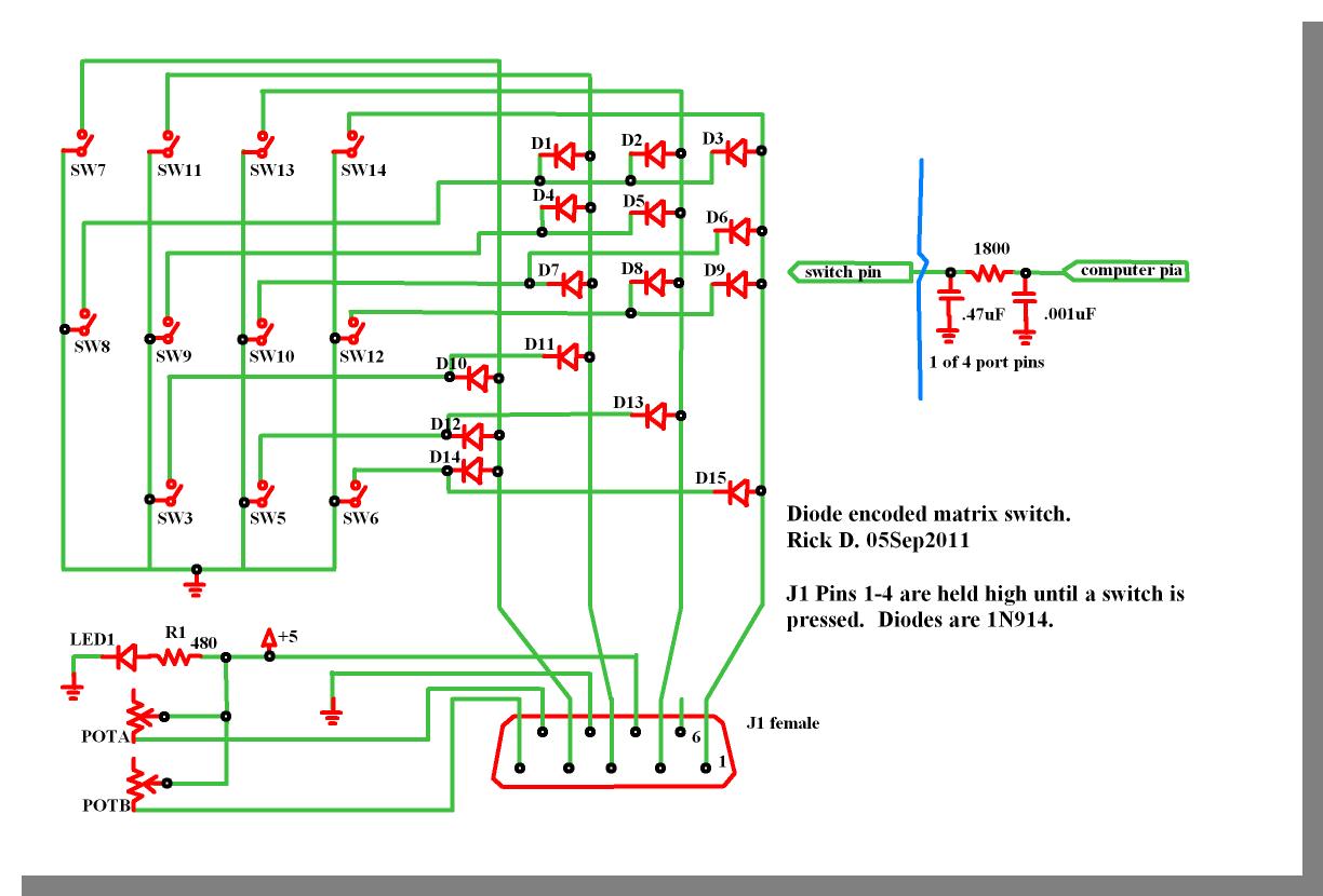 Diode matrix schematic. Diode matrix schematic.Then came the rack board with the monitor, switch board, 800XL(a future raspberry pi), and power supply mounted. 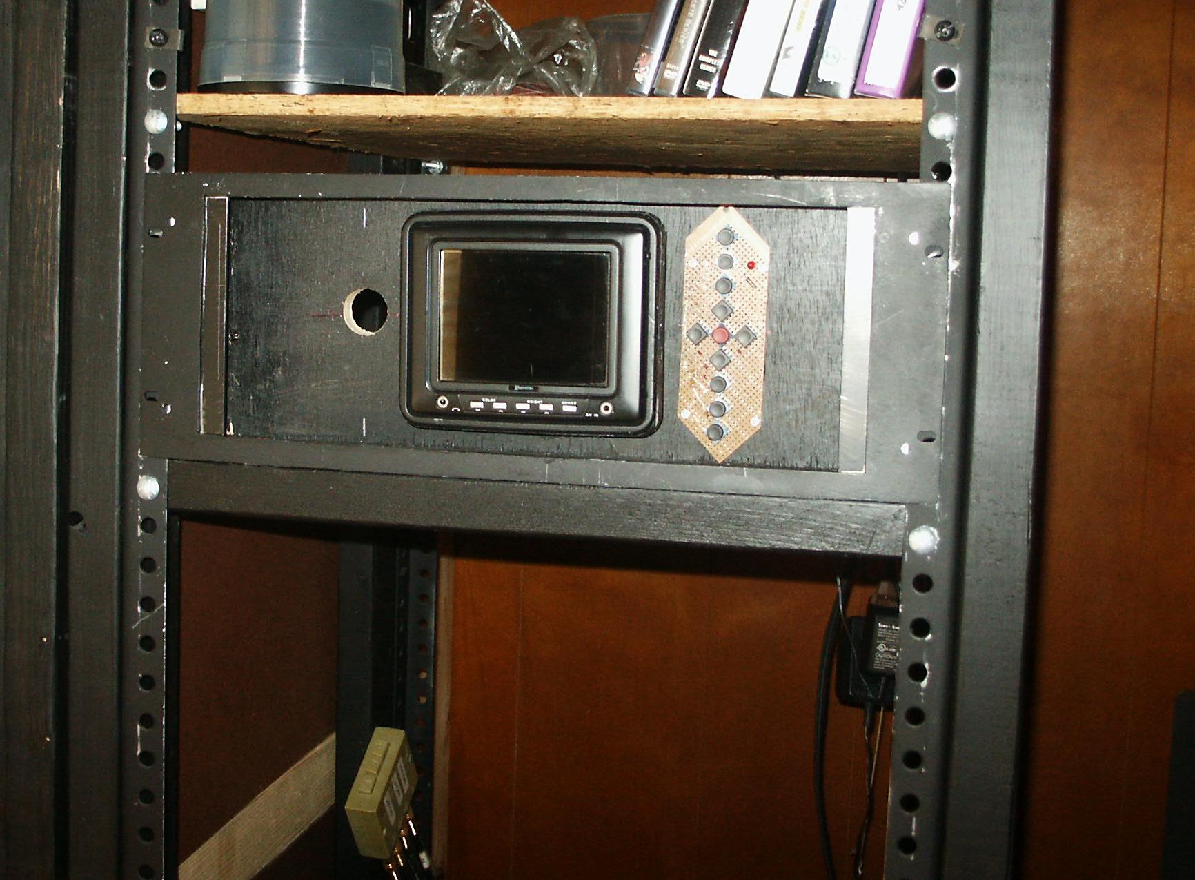 Front A. - - - Front A. - - -
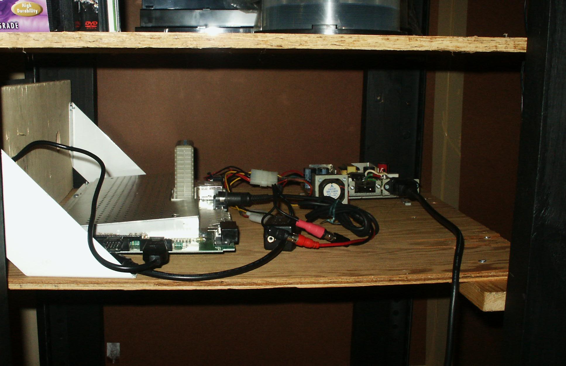 Interior A. Interior A. |
|
LED Head: 18Nov2007. Once of the electronics wall art/ornaments I have built from Electronics Now July 1994. The one thing I never liked is that it spends too much time frowning. How I resolved that and fixed errors in the schematic and pcb is Here. Visible Relay: I loved the Electronics Ornaments in the Dec 1993 Radio-Electronics magazine. I thought it could use a couple more in that line, so I have designed the first..an electronic visible RELAY. I hope to get this in Nuts and Volts magazine. The article has a confusing mix of using +5 and +12 volt supplies. I have only ever used +5(my relay only uses +5). The only link to the Ornaments and Glitter Globe kits was at e-clec-tech.com, but they look to be gone. 2600 512-in-1 cart: My interest in Atari lead me to find info and a pcb for a 2600 game console 512(programs) in 1 cart. But the pcb was in MS Visio format. What a pain to extract out. I had to go over and redo both sides to something I could make a circuit board from. The main site is here. I did not like the final result, so I did not assemble it. One day I want to do something much more up to date. Making PCBS:The method I use most uses the PNP Blue sheets. I use an Object Editor Program to recreate the pcb with scalable objects. I start by using an image for the background that I size so .1" pin spacing of ICs fits. Then I use layer tabs for lines(side 1), lines (side 2), and vias. I add project labels to each layer so I have text that must read right when printed(bottom layer text is reversed while drawing). Things to remember for home made boards is to never put thru holes under other parts. Make the traces as wide as will reasonably fit. Hairline traces will disappear when etched. No trace runs between IC legs and other narrow parts when possible. Once it is all done, I turn on only 1 layer, make lines black, and copy all layers to another page. I convert it to an image 16 color/600 dpi, and print. Then I do layer 2. I edit and reprint until both sides look and match exactly(toner side to toner side). Try placing the parts to check for spacing and lead placement. Applying PNP BLUE: I place a silicon baking sheet on a metal surface. Then the PCB, no fingerprints! I lay down the PNP sheet with clearance all around(toner side down). The text must read correctly! Look at the PNP on the copper board. See how there is a frosted appearance? Remember this for later. With a heated Iron on about 30%(moderately low), place it on the PNP, using fingers away from the iron to hold it in place. Taking the weight off of the | iron, then pressing lightly, move the iron around the PNP where the center of the iron covers the entire pattern area. Do not press hard, the toner will smear. Once the sheet is tacked down, I will cover it with copy or parchment paper to make sliding the iron easier. For a few minutes, continue heating the pattern. The bump the temp to about 50%. Slide the iron around the sheet for a few more minutes. If the PNP crinkles a lot, it got too hot. Lift the iron and any paper, but NOT the PNP! Careful, the copper board will get very hot. Has the pattern gotten darker and/or clearer? Keep heating the pattern until it all looks like this. After five minutes-ish(most is o.k., darker at the edges is important.) Once it reaches this stage, put aside the iron and let the PNP sheet and pcb cool. Once it cools down some, run it under cold water. When the board is cold, start at one corner and curl/peel the PNP away from the board slowly. All of this may take practice. But works very well. For Side Two, if there is one...Find three or four small thru holes spread around the board. Drill them out and clean them smooth. Use the method above, using the holes to align the PNP sheet, you can also poke the holes through the sheet. The more accurate at making all of the locator holes align, the better the final result will be. Again follow the method above to iron on the PNP sheet. I cover any large areas of copper with electrical tape or spray paint. Do not cover the traces. Also, now is the time to repair any broken or thin traces. I use an ultra fine paint brush and plastic model paint in tiny jars(I like yellow), but do one side, then let fully dry before working on side two. Check and recheck. The paint will resist the etching process. The pcb lacquer pens don't work. I use various blades to clear the space between traces. No shorts! Soldering in the parts:Examin the etched board. Look for etched traces and cracks. These need to beefed up with solder and/or wire bridged. You can also check each trace to verify continuity with a meter or led+battery. On a single sided board its very easy. Solder in the parts, smallest(most difficult) to largest. Just make sure the joints are all good. On a double sided board, you start by soldering the thinest parts first. Solder in any ICs last when ever possible. Sometimes it is not. For all thru hole parts with leads, make sure that you solder the lead on sides that have traces connected to the pad, it may be either layer or both. For parts that cover the hole, you take a thin wire, feed it through the hole, fold down along the trace(s), and solder to the trace(s)-not the pad. Then insert the part and solder the pin side to the pad. If you have a part with higher current, add a feed thru via alongside the pin when designing the board. |
|
GAL BLASTER: My interests lead me to wanting to do some GAL burning. I didn't need an expensive burner handling 30000 numbers. Just a dozen common types. I finally found GAL BLASTER. But the image was a low rez. The eagle schematic had errors. The pcb image had parts on top of others. Sigh. Spent time cleaning it all up. The resultant images are here. The main site Here Oct07:Still working on this. There seemed to be some major errors in the schematic and pcb. Mostly works, but the programming voltage is always .02xx. Looks like the output of the d/a chip is tied to +5 volts instead of the op amp. Sigh. Don't like working on and fixing some one elses project. And apparently few have tried to make it. |
(18nov07)Well, digging deeper shows the DAC can be connected in reverse to make it a voltage stepper. So the schematic and pcb are right. Fixed a trace(sigh) and now I get 9.5V at the the programming pin. Too low. But can't read a gal. Looks like data pin 1 has a fault. Fixed that I think. Only problem is the programming voltage never gets above 9.5. Sigh. Can't tell if I am actually reading gal data even. What does a blank gal look like? (2011)I have redone this schematic without the voltage stepper, etc. Instead, I am making a target board for the gal I want, and it programs the variable voltge out with a resistor. Will find the time to make one day. 2019:I think some of the programmers I now have will do gals. Have to check. |
|
Schematic and PCB designer software. For the longest time I did all of the design by hand. Having software on the PC greatly eases the design phase, particularly as my stuff gets more complex. There are 2 programs that are mostly used to do this EAGLE and EXPRESSPCB. Both have free versions. BUT...in any event, I still have to take the pcb, and recreate them using an object drawing pain so I can make proto pcbs here at home...another major PITA. One thing I am playing with is a program that takes an image and converts it to meta object connected lines. A lot of them. EXPRESSPCB is the software I use. I think its free only. And a little more user unfriendly. There are two programs, the schematic designer where you draw the schematic first using logic parts. And the PCB designer where you literally have to redraw the entire schematic over again using physical parts. You place the parts where you want them. Then you run wire traces(set to .03 inch or so) to every pin you used in the schematic. While an autorouter would be nice, it has a great feature where it can highlight all of the pads that are connected together in a netlist from the schematic. Its very easy to create custom parts. Almost all I use I have created because I want parts with pads big enough for homebrew making and user soldering. It is easy to create pcbs larger than 6 x 6 inches, the average size for hobbyists that have to use through hole parts. Schematics can cover several sheets, one sheet does not hold much. I would like a few features in the software: align parts/even spacing, group change of traces or pin pads, free rotate of parts. Creating a prototype pcb involves displaying top and bottom layers, getting a screen cap, loading into an object editing program, and recreating the pads and traces again. Adding in alignment triangles so the two sides align. Then print and edit till its right. |
I have now done three orders for circuit boards with them and I rate them A++!. Software is now XP and higher. I rate the software a B+. If they had a $49 enhanced version, I'd buy it. Note that there have been no major enhancements in too many years. It needs fully rotatable parts urgently. It is a PITA to have to create a new part for each angle. You can't even create a clock face with LEDs around the perimeter without juggling the pads! I had to use clear plastic to draw 12 lines with a marker to tape to the screen. Then I could place parts and make news ones as I had time. Sigh! I am looking into alternative programs. Eagle has several paid versions as well. This was the first software I played with. It looks to be a bit better in that it has an autorouter for the pcb traces. Part creation in the light version wasn't available, but now is. However, I can't give this one high marks for the hobbyist/minimal user due to several limitaions. Mostly, the largest pcb you can create is about 2 x 3.5 inches. Fine if you are using .5mm pin pitch smd parts, but not for through hole-its only big enough for a couple of chips. And only one schematic sheet. Fine for the tiny board, but nothing else. If you use this freebie for anything commercial, you have to pay a $49 registration fee. Which gets you nothing. No bigger board. To get that will cost you between $400 and $600. Far too expensive for the hobbyist plus. I don't think I could ever sell enough boards to pay for this. The $49.00 version should get an enhanced hobbyist+ version. The stuff I did in Eagle I have now redone in EXPRESSPCB. I only use this software to export/print stuff done by others. I then recreate it in EXPRESSPCB. They have versions for major OSes. I rate the software a D. PCBPOOL is a pcb service I have not even looked at. They are based in Ireland. |
|
Sources & Publications: !!! *** REVISED ***!!! | Nuts and Volts Magazine A long time favorite of mine. Has a lot of hobbyist articles. Didn't succumb to all adverts like others. Jun07:Still the best. But don't like the new format. I actually liked scanning the text classified adverts, that section is now gone. So is the fun. So is my advertising. Wonder what the thousands of others did. |
 |
Circuit Cellar Magazine Was a long time favorite of mine. Has a lot of hardware articles-but leaves a lot to the builder. Has become more of a Engineering digest. I only buy issues that appeal to me now. |
 |
Radio Electronics / Electronics Now / Poptronics all now deceased. Sigh. I want to catalog the really great stuff one day. I download the issues I want when I have time. Most scans cut off the spine text. |
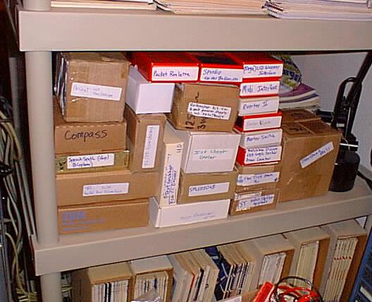 |
Project Boxes A photo of many of the projects in the works. Most are awaiting time and parts. 2019..many have been retired. Time marches on. |
|
ELEKTOR.... I really like this GB import. Has a lot of great projects, classes, tutorials, kits, and PCBs. Usually bi-monthly, but is my favorite. I used to buy it at FRYs, but have taken out a subscription for many years now. |
|
Electronics World is another good GB magazine. Jun07:Well, WAS. I eventually tired of it. Not enough electronics. |
|
MAKE.... I really like this one too. If you like making stuff your self, this is a great choice. Has a sister pub, called Craft. They also do mostly mini Maker Faires through out the year. These are the most overwhelmingingly(sic) fantastic events one could go to. I now only buy it when I think about it. |
|
|
| EveryDay Practical Electronics is a good GB mag. June07:Well, WAS. I have gone back thru the last 4 years and have only found 6 or so really good projects. Most are "everyday". Few are fantastic, such as the USB Power Injector(Dec06) I built. Does have a lot of nice articles on using PICs. I only buy it when I want. |
|
Retro Gaming is a good GB mag on older computer and games sytems. Jam packed. With cover CD. Jun07:I dropped this one too. I decided I had enough info on the systems I really like. |
|